
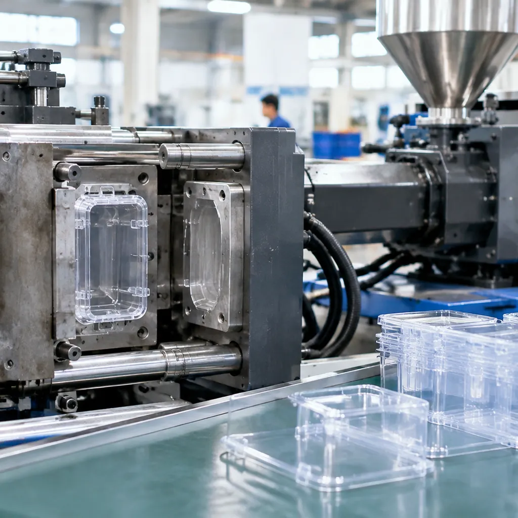
Are you struggling with defects, warping, or cloudy finishes in your production run?
Mastering PC injection moulding is notoriously difficult—its high melt viscosity and tight processing window leave zero room for error.
Having spent years optimizing engineering plastics on the shop floor, I know exactly what it takes to achieve high-precision, crystal-clear polycarbonate parts. In this guide, you’ll learn the precise temperature settings, mold design principles, and troubleshooting tips needed to eliminate defects and streamline your manufacturing process.
Let’s dive right in.
Why PC Is Tough to Mold
Polycarbonate delivers unmatched optical clarity and structural resilience, but it is easily one of the most unforgiving resins to run on the production floor. As a professional injection molding manufacturer and supplier, we know firsthand that processing PC requires a narrow operating window. Miss your numbers by a fraction, and you will run into severe cosmetic flaws or structural failures before the part leaves the tool.
High Melt Viscosity and Flow Resistance
Unlike semicrystalline polymers such as polypropylene or nylon, polycarbonate has an amorphous molecular structure with stiff polymer backbones. This structure creates massive internal resistance during flow.
- Low shear sensitivity: PC maintains high melt viscosity even under aggressive injection speeds. Ramping up shear rate barely thins the material.
- High pressure requirement: Filling thin walls or long flow paths demands substantially higher injection pressures and rigid machine clamping force to prevent short shots and premature freezing.
- Thermal sensitivity: Forcing viscous resin through restrictive gates causes localized frictional overheating, degrading the polymer matrix instantly.
Hygroscopic Nature and Moisture Sensitivity
Polycarbonate absorbs ambient moisture rapidly directly out of the bag or hopper.
- Hydrolysis risk: PC reacts with moisture at melt temperatures above 260°C (500°F). Water molecules cleave the carbonate linkages in the polymer chains.
- Irreversible degradation: Moisture does not just cause cosmetic silver streaks; it causes chemical degradation that permanently reduces molecular weight and mechanical toughness.
- Strict tolerance: Pellets must maintain a moisture content below 0.02% (ideally under 0.015%) prior to entering the feed throat.
High Impact Strength vs. Notch Sensitivity
PC is famous for being virtually unbreakable, yet parts frequently crack in the field due to notch sensitivity.
| Property Factor | Shop-Floor Reality | Design & Processing Rule |
|---|---|---|
| Bulk Impact Resistance | Outstanding energy absorption in uniform walls. | Maintain consistent wall transitions across the entire part. |
| Notch Sensitivity | Sharp corners concentrate stress and cause catastrophic brittle failure. | Apply an inside corner radius equal to at least 50% to 60% of wall thickness. |
| Molded-In Stress | Quick freezing leaves high residual stress around gates and bosses. | Use elevated mold temperatures to minimize molecular orientation. |
Pre-Drying Polycarbonate Resin for PC Injection Moulding
Moisture is the primary enemy of polycarbonate on the shop floor. Skipping or rushing the drying cycle directly compromises the integrity and aesthetics of your parts before the resin even hits the screw.
Why Moisture Ruins PC Parts
Polycarbonate is inherently hygroscopic. When wet resin enters a heated barrel, water molecules react with the molten polymer chain in a process called hydrolysis in PC molding.
- Chain Scission: Heat and water break down the polymer backbone, drastically slashing molecular weight.
- Loss of Toughness: Impact resistance plummets. Parts become brittle and crack under minimal load.
- Cosmetic Failure: Vaporized water creates splay, cloudiness, and silver streaks across clear surfaces.
- Irreversible Damage: Unlike simple surface cosmetic defects, hydrolyzed PC cannot be salvaged or re-pelletized into high-grade parts.
Partnering with an experienced 注塑成型树脂供应商 ensures you receive raw material packaged in moisture-barrier bags, but proper floor handling remains critical.
Recommended Drying Temperatures and Dew Points
To prevent thermal degradation and guarantee impact strength, target a final moisture content below 0.02% (ideally under 0.015% for optical grades). Standard hot-air ovens will not work; always run a desiccant or vacuum dryer.
| 参数 | 推荐设定 |
|---|---|
| PC Resin Drying Temperature | 120°C – 125°C (248°F – 257°F) |
| Drying Time | 3 to 4 hours (minimum) |
| Air Dew Point | -40°C (-40°F) or lower |
| Max Barrel Residence Time | < 15 minutes at processing heat |
Do not over-dry above 130°C for extended shifts, as this discolors natural resin and causes pellet clumping in the dryer hopper.
Signs of Under-Dried Resin on the Shop Floor
Spotting wet material early saves hours of purging and prevents scrap piles during 树脂注塑成型 runs:
- Frothing Purge Puddle: When you perform an air shot, the purge puddle froths, foams, or crackles with visible popping bubbles.
- Silver Streaks and Splay: Distinct fan-shaped streaks appear radiating outward from the gate.
- Drooling at the Nozzle: Melt viscosity drops unexpectedly, leading to excessive stringing and nozzle drool between cycles.
- Mica-Like Flakes: The part surface shows shiny, delaminated flecks under bright inspection lighting.
Mold and Tooling Design Rules for PC Injection Moulding
Polycarbonate is notoriously stiff and unforgiving inside a tool. When we cut steel for PC injection moulding, our mold design must account for high viscosity plastic molding, high filling pressures, and sensitive optical surfaces. Skimping on draft angles, runners, or vents leads directly to scrap parts, splay, and internal stress.
Draft Angle Requirements for Clear Parts
Polished optical surfaces stick hard to mold walls. Without adequate draft, ejector pins will push witness marks right through the part, or you will scuff the surface on release.
- Standard polished clear surfaces: 最低 1.5° to 2° per side.
- High-depth optical areas: 使用 2° to 3° to ensure a clean release without drag lines.
- Textured faces: Add an extra 1° of draft for every 0.025 mm (0.001 in) 纹理深度。
- 肋、凸耳: Use at least 1° to 1.5° to avoid sticking, keeping rib thickness at 40% to 50% of the nominal wall to avoid sink marks.
Gate Sizing and Runner Types for High-Viscosity Resin
PC resists flow, so small pinpoint gates choke the fill and create massive shear-induced stress.
- Runner design: Always specify full-round runners with a diameter between 6 mm and 10 mm. Avoid half-round runners; they restrict flow and cause premature freeze-off.
- Gate thickness: Size gates to 60% to 70% of the nominal wall thickness. Tab gates, fan gates, and edge gates work best.
- Hot runners: Internally heated hot runners work well, but you need precise valve-gate tips with individual PID temperature loops. When running high-cavitation tools, pairing your tool with a rigid, high-pressure 用于销售的注塑成型机 ensures you deliver the high injection pressures PC requires without blowing out the parting line.
Proper Venting Depth to Avoid Burn Marks and Trapped Gas
Because PC requires fast injection speeds and high melt temperatures, trapped air ignites quickly, causing diesel burns and short shots.
- Vent depth: Machine vent lands to 0.038 mm to 0.050 mm (0.0015" to 0.0020"). PC has a high melt viscosity, so it will not flash at this depth.
- Vent land length: Keep the vent land short at 1.2 mm to 1.5 mm, then dump straight into a relief channel vented to the atmosphere that is at least 0.8 mm to 1.0 mm deep.
- Vent placement: Place vents around the entire perimeter, directly opposite gates, and at the end of every weld line and blind rib.
Cooling Channel Placement for Uniform Shrinkage
Polycarbonate has a relatively low mold shrinkage rate (0.5% to 0.7%), but uneven cooling creates immense molded-in residual stress that leads to post-mold cracking.
- Pitch and depth: Place cooling lines 1.5 to 2 times the channel diameter away from the cavity surface, with a pitch spacing of 2 to 3 diameters.
- Core and cavity balance: Run dedicated cooling circuits for the core and cavity halves. The core side usually requires higher flow rates or slightly higher coolant temperatures to balance heat extraction and prevent post-ejection part bowing.
- Turbulent flow: Maintain a Reynolds number above 4,000 across all channels to ensure rapid, uniform heat exchange.
| Tooling Parameter | Recommended Specification | Primary Defect Prevented |
|---|---|---|
| Clear Part Draft | 1.5° – 2.0° minimum | Drag marks, haze, ejection distortion |
| Gate Land Length | 0.75 mm – 1.0 mm | Excessive shear stress, gate blush |
| Vent Depth | 0.038 mm – 0.050 mm | Dieseling, short shots, burned edges |
| Runner Diameter | 6.0 mm – 10.0 mm (Full Round) | High pressure drop, cold slugs |
| Cooling Line Distance | 1.5x – 2.0x channel diameter from cavity | Uneven shrinkage, part warpage |
Dialing In Machine Settings for PC Injection Moulding
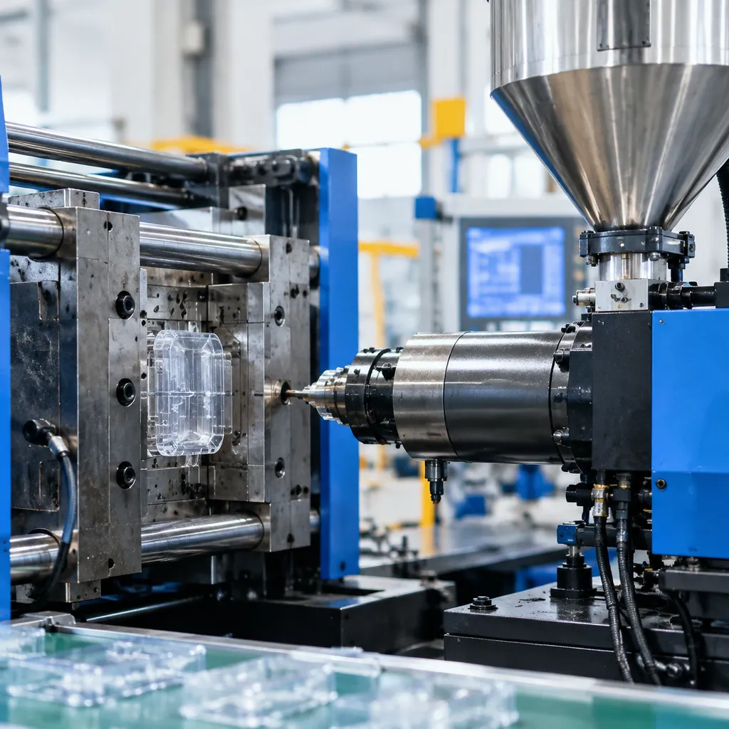
Setting up a press for polycarbonate leaves zero room for guesswork. Because of its stiff flow and sensitivity to heat, running stable PC injection moulding requires a balanced thermal profile, consistent packing, and controlled shear. Dialing in your process parameters right from the start protects parts against internal stress, premature cracking, and structural failure.
| Parameter Zone | 推荐范围 | 用途 |
|---|---|---|
| Rear Zone (Feed) | 260°C – 280°C (500°F – 535°F) | Prevents premature melting and screw bridging |
| Middle / Front Zones | 280°C – 310°C (535°F – 590°F) | Establishes uniform melt viscosity |
| Nozzle Tip | 275°C – 305°C (525°F – 580°F) | Stops drooling while preventing cold slugs |
| 模具温度 | 80°C – 120°C (175°F – 250°F) | Minimizes molded-in stress and improves finish |
| 保压 | 50% – 70% of injection pressure | Compresses melt to prevent sink marks |
| 背压 | 0.5 – 1.0 MPa (70 – 145 psi) | Ensures melt homogenization without shear heating |
Barrel Temperature Zones and Nozzle Setup
We always aim for a flat-to-ascending heat profile along the barrel. Polycarbonate requires high energy to melt, but letting material bake in the barrel leads to severe thermal degradation.
- Nozzle control: Keep the nozzle roughly 5°C to 10°C cooler than the front zone to eliminate drool. Always use reverse-taper or shut-off nozzles if stringing persists.
- Residence time: Keep cycle times tight so the resin does not sit in the barrel for more than 5 to 8 minutes. Stagnant melt degrades, loses molecular weight, and drops impact resistance.
Mold Temperature Control for Structural Integrity
Cold tools are the enemy of strong polycarbonate parts. When PC hits a cold mold surface, the outer skin freezes instantly, locking massive residual stresses inside the part walls.
- Run hot water or oil units to keep the mold between 85°C and 115°C.
- High tool temperatures promote proper crystal relaxation, boost surface gloss, and eliminate premature weld line failure.
- Imbalanced temperatures between the core and cavity halves will cause immediate part warping as thick sections cool unevenly.
Injection Speed and High-Pressure Holding Stages
Polycarbonate freezes off rapidly, so injection velocity must be aggressive enough to fill the cavity before gate freeze, yet profiled carefully to avoid shear burns.
- Velocity profiling: Start with a moderate injection speed through the gate to prevent jetting, ramp up to high speed through the main cavity body, and drop down just before the switchover point to avoid flash.
- Packing and hold: Switch to hold at 95% of cavity fill. Apply solid holding pressure—typically 60% to 80 MPa—to feed volumetric shrinkage. Incorrect transitions often trigger cosmetic and structural flaws; catching these early requires understanding common 注塑成型缺陷及其排除故障 to stabilize production quickly.
Screw Recovery Speed and Back Pressure Settings
Over-shearing PC during plasticizing generates excessive frictional heat, destroying optical clarity and degrading the polymer chains.
- Screw speed (RPM): Keep peripheral screw speed below 0.2 m/s (roughly 30 to 60 RPM depending on screw diameter). Slow, steady rotation keeps the melt uniform.
- Back pressure: Use low to moderate back pressure. Set just enough pressure to ensure consistent shot weight and eliminate trapped air in the melt. Excessive back pressure creates frictional hotspots that lead directly to yellowing and splay marks.
Troubleshooting Common PC Injection Moulding Defects
When processing polycarbonate, running into cosmetic or structural flaws is part of the daily grind. As a professional injection molding manufacturer and supplier, we see these issues constantly on the floor. Most issues stem from viscosity shifts, trapped gases, or thermal breakdown. Here is how we diagnose and fix these problems in real-time production. You can review our broader guide on 注塑成型缺陷及其排除故障 for baseline machine routines.
Fixing Silver Streaks and Moisture Splay
Silver streaks usually point to one of two culprits: trapped moisture or shear overheating.
- Moisture splay: Looks like feather-like trails across the surface. Check the hopper dryer immediately. Polycarbonate needs a moisture content below 0.02%. Ensure your dryer hits 120°C (250°F) with a dew point of -40°C.
- Shear splay: Appears near gates. Lower the injection speed across the gate-entry zone, reduce back pressure, and enlarge restrictive nozzles or sprue orifices to ease shear friction.
Eliminating Bubbles, Voids, and Sink Marks
Thick-walled PC parts shrink unevenly, creating interior vacuum voids or exterior sink marks.
- Vacuum voids (clear parts): Raise the hold pressure and extend the pack time. Increase the cushion size to 3–5 mm to ensure pressure transfers completely through the gate before freeze-off.
- Gas bubbles: Trapped air bubbles inside the melt mean decompression (suck-back) is too high, pulling air past the nozzle tip. Reduce suck-back distance and speed.
- 缩水纹: Drop the melt temperature slightly, increase gate sizes to prevent early gate freeze, and lower the mold temperature on the non-appearance side.
Preventing Flow Marks and Jetting
Polycarbonate freezes fast due to high melt viscosity. If the flow front stalls or shoots unchecked into the cavity, visual blemishes appear immediately.
| 缺陷 | 根本原因 | Practical Shop-Floor Fix |
|---|---|---|
| Flow Marks / Halos | Cold melt front hesitation | Raise mold temperature by 10–15°C, increase primary injection speed, and optimize hot runner nozzle tip heat. |
| 射出斜流 | Melt shoots through gate without wall contact | Use a profiled injection speed (slow-fast transition), change to an edge or fan gate, or angle the gate toward a cavity pin or wall. |
Stopping Premature Cracking Caused by Molded-In Stress
Polycarbonate has notorious notch sensitivity and retains high internal stress if packed too hard or cooled unevenly. This leads to cracking during assembly, solvent exposure, or general handling.
- Lower excessive packing: Reduce pack and hold pressures to the minimum level needed to prevent sinks.
- Raise mold temperature: Running mold temps between 85°C and 120°C allows polymer chains to relax naturally, cutting residual stress dramatically.
- Radius sharp corners: Sharp internal corners act as direct stress risers. Add a minimum radius of 0.5 mm to 0.6 times wall thickness on all transitions.
Fixing Yellowing and Thermal Degradation
Yellow tints and brittle edges mean the PC resin stayed too hot for too long inside the barrel, breaking down the polymer chains.
- Lower barrel temperatures: Keep temperatures strictly within the 280°C to 310°C window, depending on the grade.
- Right-size the shot capacity: Shot weight should use 35% to 65% of the machine's total barrel capacity. If the barrel is oversized, resin residence time exceeds the safe 5-minute limit, leading directly to discoloration and reduced impact strength.
- Clean hot runners: Remove degraded resin and charred buildup by purging with high-viscosity acrylic or a dedicated polycarbonate purging compound.
Annealing and Post-Mold Stress Relief
Internal stresses are an unavoidable reality in PC injection moulding. High melt viscosity combined with rapid mold cooling locks severe molecular orientation into the part. If left unchecked, these frozen-in stresses lead to delayed warping, micro-crazing, and catastrophic cracking under everyday loads or chemical exposure.
When Your PC Parts Need Annealing
We do not anneal every part that leaves our presses, but specific part designs and service conditions make stress relief non-negotiable:
- Heavy or uneven wall sections: Thick-walled components cool non-uniformly, concentrating stress right at the core-skin boundary.
- Secondary operations: Parts requiring drilling, tapping, ultrasonic welding, or snap-fit assemblies.
- Chemical environment exposure: Components exposed to oils, greases, cleaning agents, or bonding adhesives.
- Optically critical lenses: Transparent parts where molded-in birefringence distorts light paths.
Even when sourcing reliable 用于注塑的散装塑料颗粒, aggressive injection speeds and high packing pressures can lock extreme stresses into the core. Annealing gives those polymer chains the thermal mobility they need to relax.
Oven Temperature Cycles and Cooling Rates
Annealing polycarbonate requires strict thermal discipline. Heating too fast causes part distortion, while cooling too quickly simply reintroduces the exact stress you are trying to eliminate.
| 阶段 | Process Target | Guidelines |
|---|---|---|
| Pre-Heating | Ramp up gradually | Ramp up to temperature at 10°C to 15°C per hour to prevent thermal shock. |
| Soaking Temperature | 120°C – 130°C (248°F – 266°F) | Keep it roughly 10°C to 15°C below the heat deflection temperature (HDT) to stop parts from sagging. |
| Soaking Time | 1 hour per 5 mm of wall thickness | Start the timer only after the entire oven chamber and part core reach the set temperature. Minimum soak: 2 hours. |
| Cooling Cycle | Slow, uniform cooldown | Cool inside the oven at a rate of 8°C to 10°C per hour until parts fall below 60°C (140°F) before removal. |
Quick Solvent Dip Tests for Residual Stress Inspection
You cannot detect locked-in stress with a visual check under normal room lighting. We use simple shop-floor solvent dip tests to verify stress levels within minutes:
- Prepare the Reagent: Mix a standard solution of 1:1 n-propanol and toluene, or use pure ethyl acetate for an aggressive evaluation.
- Submerge the Component: Immerse the clean, room-temperature PC molding into the bath for 1 to 3 minutes.
- Inspect for Crazing: Remove, rinse thoroughly, and immediately check the component under focused LED lighting.
- Pass: The surface stays smooth, clear, and crack-free.
- Fail: Instant cloudiness, visible micro-cracks, or deep crazing around gate entries, ribs, and screw bosses indicate dangerous molded-in stress that demands immediate oven annealing or tool tuning.
Material Selection and Production Cost Tips in PC Injection Moulding
Balancing part performance with resin expenses and press cycle times directly controls your margins. We run millions of polycarbonate components each year, and controlling production costs always comes down to choosing the correct resin grade, managing regrind cleanly, and shaving critical seconds off thick sections. As our facility 扩大模具成型产能, we use these field-tested guidelines to keep yield high and unit costs competitive.
Standard vs. Optical vs. Flame-Retardant PC Grades
Selecting the wrong resin grade drives up cycle times and scrap rates instantly. We evaluate grades based on melt flow rate (MFR), transparency requirements, and agency compliance:
| PC Grade | Typical Melt Flow (g/10 min) | Primary Characteristics | 常见应用 |
|---|---|---|---|
| Standard / General Purpose | 6 – 15 | High impact resistance, balanced stiffness, good dimensional stability. | Enclosures, structural frames, industrial covers |
| Optical Grade | 10 – 30 | Ultra-pure melt, minimal molecular variation, >89% light transmittance, low haze. | LED lenses, light pipes, sensor windows, eyewear |
| Flame-Retardant (UL94 V-0) | 5 – 12 | Formulated with non-halogen or brominated additives; lowers notch impact slightly. | Electrical housings, junction boxes, EV components |
Regrind Limits and Blending Rules Without Losing Clarity
Polycarbonate suffers thermal and hydrolytic degradation every time it passes through the barrel. To protect mechanical strength and transparency:
- Optical and clear components: Limit regrind to 0% to 5%. Anything beyond 5% introduces yellow tint, micro-gels, and cloudiness that ruin light transmission.
- Opaque and black parts: Blend up to 15% to 20% regrind with virgin resin. Ensure the regrind has passed through only one heat history.
- Dust extraction is mandatory: Screen out fine dust and irregular regrind flakes. Uneven flake sizes cause erratic screw recovery and inconsistent melt pools.
- Re-dry thoroughly: Treat regrind as saturated resin. Dry it at 120°C (250°F) for at least 4 hours before blending with dried virgin pellets.
Cycle Time Reduction Strategies for Thick-Walled Parts
Thick-walled sections in PC injection moulding hold heat stubbornly, often dragging cycle times past 60 to 90 seconds. We apply these shop-floor tactics to cut cycle times without causing voids or sink marks:
- Core out heavy walls: Redesign thick bosses and ribs into uniform nominal walls (ideally 2.5 mm to 3.5 mm) with coring pins.
- Install high-conductivity inserts: Swap tool steel in hot core areas for beryllium copper or AMPCO alloys to transfer heat to cooling channels 3 to 4 times faster.
- Profile holding pressure in stages: Apply high initial pack pressure to compress the melt, then step pressure down by 30% to 40% as the gate freezes to shorten hold time without triggering sink marks.
- Ensure turbulent cooling water flow: Run high-flow chillers to maintain a Reynolds number above 4,000 in your mold circuits. Fast-moving water pulls heat far more aggressively than cold, stagnant water.
FAQs About PC Injection Moulding
Running polycarbonate on the shop floor often brings up recurring challenges around heat, clarity, and structural fatigue. As a professional injection molding manufacturer and supplier, we see these questions all the time across production lines worldwide. Here are direct answers based on daily shop-floor processing experience.
What is the ideal mold temperature for PC?
For standard PC injection moulding, the target mold temperature generally ranges between 80°C and 120°C (176°F to 248°F).
- Thin-walled or standard technical parts: Run between 85°C and 95°C to balance cycle time and proper mold filling.
- Thick sections, optical components, or high-stress parts: Increase to 100°C to 120°C using an oil heater or pressurized water unit.
Running the tool cold freezes the high-viscosity melt prematurely, creating severe residual stress and dull surface finishes. If you are upgrading your tooling setup or seeking dependable production equipment, pairing the right mold heater with a rigid 用于出售的二手塑料注塑机 helps maintain the clamp rigidity and thermal stability necessary for tough engineering resins.
Why do my transparent PC parts look cloudy?
Haze or cloudiness in clear polycarbonate parts typically stems from three root causes:
- Moisture entrapment (Hydrolysis): Under-dried resin causes micro-foaming and chemical breakdown in the melt. Always dry raw pellets to a moisture level below 0.02% using a desiccant dryer.
- Low mold surface temperature: If the cavity wall is too cold, the skin freezes instantly without replicating the high-polish finish of the cavity, scattering light.
- Melt degradation or contamination: Contamination from incompatible resins (like acrylic or general-purpose polystyrene) or excessive barrel residence time breaks the polymer chains, resulting in milkiness or yellowing.
Can I use regrind polycarbonate for optical parts?
We strongly advise against using regrind for lenses, light guides, light diffusers, or medical housings requiring strict optical clarity injection molding 标准。
- Thermal history causes thermal degradation each time the resin passes through the screw, dropping the molecular weight.
- Regrind introduces microscopic dust, uneven pellet sizing, and localized char that scatter light and reduce overall light transmission.
- For non-critical, opaque, or black housings, a clean regrind blend of 10% to 15% can be managed, but optical-grade runs should remain 100% virgin resin.
How do I stop PC parts from stress cracking around screw bosses?
Screw bosses are prime zones for stress cracking polycarbonate due to sharp corners, knit lines, and hoop stresses from fasteners. To eliminate cracking in these areas:
- Increase root radii: Always add generous fillets (at least 25% to 50% of the wall thickness) at the base of the boss to prevent notch-sensitive crack propagation.
- Adjust wall thickness: Keep the boss wall around 60% of the nominal wall thickness to prevent sink marks, voids, and localized molded-in stress.
- Raise mold temperature: Running the tool hotter allows the molecules to relax as the tool packs, significantly dropping residual stress near knit lines.
- Switch fastener types: Avoid standard self-tapping sheet metal screws. Use thread-forming screws designed specifically for plastics, or transition to ultrasonic brass inserts to eliminate continuous hoop stress.

 Belarusian
 English
 French
 German
 Spanish
 Italian
 Polish
 Russian
 Japanese
 Korean
 Arabic
 Dutch
 Portuguese
 Swedish
 Norwegian
 Armenian