

What Is an Injection Mold?
An injection mold is a precision-engineered tooling system used to shape molten plastic into consistent, high-quality parts. In our facilities, the mold is the core asset that defines part accuracy, surface finish, and production efficiency.
Definition and Purpose
An injection mold:
- Forms the plastic part’s final geometry (inside and outside)
- Controls tolerances, texture, and dimensions
- Enables high-volume, repeatable production with minimal variation
The mold is not just a block of steel; it is a custom-built production tool designed around your product’s requirements.
Mold vs. Molding Machine
It’s critical to distinguish between the mold (tool) and the injection molding machine:
| Item | Role |
|---|---|
| Injection mold (tool) | Creates the shape of the part; contains cavity, core, runners, cooling, and ejection system |
| Injection molding machine | Provides clamping force, melts and injects plastic, powers the mold’s opening, closing, and ejection |
We engineer and supply the injection mold, which can run on globally standard injection molding machines.
Common Types of Injection Molds
Different mold structures suit different parts, materials, and volumes:
| Mold Type | Key Feature | Typical Use Case |
|---|---|---|
| Two-plate mold | Simple design with one parting line | General parts, cost-sensitive projects |
| Three-plate mold | Separate plate for runners and parts | Multi-cavity molds, better gate positioning |
| Hot runner mold | Heated runner system, no solidified runners | High-volume, reduced waste, faster cycles |
By selecting the right injection mold type—two-plate, three-plate, or hot runner mold—we optimize your cycle time, material usage, and overall part quality for global manufacturing standards.
Core Structure: Mold Base and Plates in an Injection Mold
In any injection mold, the core structure is the mold base and plates. This is the “chassis” that keeps everything rigid, aligned, and repeatable from shot to shot. If this foundation is weak, you’ll fight flash, misalignment, and inconsistent part quality no matter how good your core and cavity are.
Mold base: the foundation
The mold base holds all major injection mold components together and transfers clamping force from the molding machine into the tool. A well-designed mold base:
- Provides rigidity so the parting line stays sealed under high injection pressure
- Holds the core and cavity plates, ejector system, and guiding system in fixed positions
- Ensures long-term dimensional stability for high-volume production
For high-precision and medical-grade parts, like those we run in our own tooling for plastic injection moulding of dental components, we don’t compromise on mold base quality or steel selection.
Top and bottom clamp plates
The top and bottom clamp plates (also called clamping plates) bolt the mold to the fixed and moving platens of the injection molding machine. Their job is simple but critical:
- Safely transfer machine clamping force into the mold
- Keep the mold halves stable during high-speed opening and closing
- Provide mounting holes, keyways, and lifting points for safe handling
If clamp plates are undersized or poorly machined, you’ll see mold shifting, misalignment, and premature wear on guide pins and bushings.
A-plate (cavity side) and B-plate (core side)
The A-plate (or cavity side) and B-plate (core side) are where the actual part geometry lives:
-
A-plate / cavity side
- Usually faces the fixed platen
- Contains the cavity side of the part and often the gate and runner system
- Drives surface finish and external shape
-
B-plate / core side
- Usually faces the moving platen
- Contains the core, internal features, boss structures, and ejector interface
- Works closely with the ejection system to release the part
Good design of these plates directly affects cycle time, part tolerance, and mold life. In high-output environments like our expanded production lines described in our overview of how plastic injection moulding works, we focus heavily on plate rigidity and alignment.
Support plates, spacer blocks, and ejector housing
Behind the main plates, several structural components keep everything aligned and give space for the ejector system:
-
Support plates
- Reinforce the B-side under high injection pressure
- Prevent plate deflection and parting-line opening
- Protect delicate areas under cores or inserts
-
Spacer blocks
- Create the gap needed for the ejector housing and ejector stroke
- Help manage mold weight and stiffness efficiently
-
Ejector housing
- Encloses and guides the ejector plates, pins, and return mechanisms
- Keeps the ejection system aligned with the core features
- Makes maintenance and replacement of ejection components easier
Together, the mold base, clamp plates, A-plate, B-plate, and support structure form a stable, repeatable platform. When we design a mold base for global customers, our priority is simple: strong enough to resist injection pressure, precise enough to hold microns, and practical enough for real-world maintenance and long production runs.
Forming Components: Core and Cavity
In any part of an injection mold, the core and cavity are the heart of the tooling. They directly define the shape, accuracy, and surface quality of your plastic part.
Mold Cavity: Outside Shape of the Part
The mold cavity is the negative shape that forms the external geometry of the product.
A well-designed cavity gives you:
- Accurate outside dimensions
- Clean surfaces and textures
- Stable tolerances across high-volume runs
For more detail on how the cavity fits into the full tool, I break this down further in our guide on the main injection mold parts and functions.
Mold Core: Inside Features and Undercuts
The mold core creates the internal features of the part:
- Holes, recesses, bosses, ribs
- Threads and snap fits
- Internal undercuts and deep pockets
Core design is critical for:
- Demolding without damage
- Maintaining wall thickness
- Avoiding sink marks and deformation
Inserts, Slides, and Lifters for Complex Geometry
When parts get more complex, we don’t redesign the entire mold — we use inserts, slides, and lifters:
-
Core/cavity inserts
- Swappable steel blocks for high-wear areas
- Easy to replace or modify for design changes or different versions
-
Slides (side actions)
- Move sideways to form side holes, side undercuts, and snap features
- Retract during ejection so the part can be released cleanly
-
Lifters
- Move at an angle to release internal undercuts
- Ideal for clips, hooks, and complex locking details
By combining a solid core and cavity with smart use of slides, lifters, and inserts, I can keep the tool compact, the cycle time fast, and the part quality consistent — even for demanding global applications in automotive, electronics, and consumer products.
Feeding System in an Injection Mold
In any injection mold, the feeding system decides how stable, fast, and repeatable your production will be. If the sprue, runner, and gate are wrong, you waste material, fight defects, and lose cycle time.
Sprue Bushing
The sprue bushing connects the injection molding machine nozzle to the mold:
- Central channel where molten plastic first enters the mold
- Needs a smooth taper for easy sprue release
- Must match the nozzle of the injection molding machine you’re using – whether new or a used plastic injection molding machine
Runners: Distributing Molten Plastic
Runners are the channels that distribute melt from the sprue to each cavity:
- Can be full-round, trapezoid, or rectangular in section
- Designed for balanced flow and minimal pressure drop
- Directly affect cycle time, part weight, and material waste
Gates: Entry Points into the Cavity
Gates control how melt enters the cavity and how the part is packed and frozen:
Common gate types:
- Edge gate – simple, good for flat parts
- Pinpoint gate – small, clean break, good for multi-cavity tools
- Submarine (tunnel) gate – automatic de-gating, ideal for high-volume
Good gate design helps reduce:
- Weld lines
- Jetting and burn marks
- Warpage and sink marks
Hot Runner vs. Cold Runner Systems
| System | Key Features | Best For |
|---|---|---|
| Cold runner | Solid runner that is ejected with the part | Lower volume, simple molds, lower tooling cost |
| Hot runner | Heated channels, no solid runner scrap | High-volume, multi-cavity, material savings |
Hot runner molds cut material waste and reduce cycle time but cost more upfront and need tighter temperature control. Cold runners are cheaper to build and easier to maintain, but you pay in extra material and sometimes slower cycles.
When I design a feeding system, I always balance:
- Part size and geometry
- Resin type
- Target cycle time and volume
- Machine size and available injection pressure
This is where you win or lose profitability on a mold.
Cooling System in a Part of an Injection Mold
In any part of an injection mold, the cooling system is what really controls part quality and cycle time. Once the melt fills the mold core and cavity, cooling channels carry water or oil through the mold base plates to pull heat out of the plastic. Well-designed channels give uniform cooling, so the part shrinks evenly instead of twisting or bowing.
I always focus on cooling layout early because it directly drives:
- Cycle time – better cooling = faster solidification = more parts per hour
- Dimensional stability – consistent wall temperature means tighter tolerances
- Defect prevention – proper cooling avoids warping, sink marks, and internal stress
Key points when designing the cooling system in injection mold components:
- Keep cooling channels close to the cavity and core surfaces, but not so close that they weaken the steel
- Use balanced, looped circuits to avoid hot spots and temperature gradients
- Match coolant flow rate and temperature to the resin and wall thickness
If cooling isn’t done right, you’ll see warp, differential shrinkage, and other defects that we often cover when troubleshooting injection molding defects and solutions. For high-volume global production, optimizing cooling channels is one of the fastest ways to cut cost per part without changing the material or the machine.
Ejection System: Releasing the Finished Part
In any part of an injection mold, the ejection system decides how cleanly and quickly your part leaves the cavity. If this section is poorly designed, you’ll see scratches, dents, and ugly ejector marks all over the product.
Key ejection components
-
Ejector pins
- Standard solution for most parts
- Push the molded part off the mold core and cavity after the mold opens
- Need correct size, number, and layout to avoid pin marks and deformation
-
Ejector sleeves
- Tube-shaped ejectors, ideal for parts around cores or bosses
- Provide uniform push around circular features
- Reduce stress concentration on the plastic part
-
Ejector blades
- Thin, flat ejectors for ribs, thin walls, or tight spaces
- Great for parts where round pins can’t be used
-
Ejector plates and retainer systems
- The ejection system is driven by ejector plates that move all pins, sleeves, and blades together
- Retainer plates lock each ejector component in place, keeping alignment stable during high-speed cycles
How to avoid marks and damage
When we design and build molds, we focus heavily on clean ejection, especially for visible surfaces and tight-tolerance parts:
- Keep ejector contact away from cosmetic or high-precision surfaces
- Use larger-area ejectors (sleeves, blades) on thin or flexible regions
- Add proper cooling channels so the part is rigid enough before ejection
- Control ejector stroke and speed to prevent bending, cracking, or whitening
- Finish and polish pin faces to reduce witness marks
A well-engineered ejection system directly impacts part quality, cycle time, and scrap rate. That’s why in our tooling projects, we treat the ejection layout as seriously as the runner system or gating strategy. If you want a complete view of how this fits into the whole molding workflow, I recommend looking at our overview of what plastic injection molding is and how it works in production.
Guiding and Alignment Components in an Injection Mold
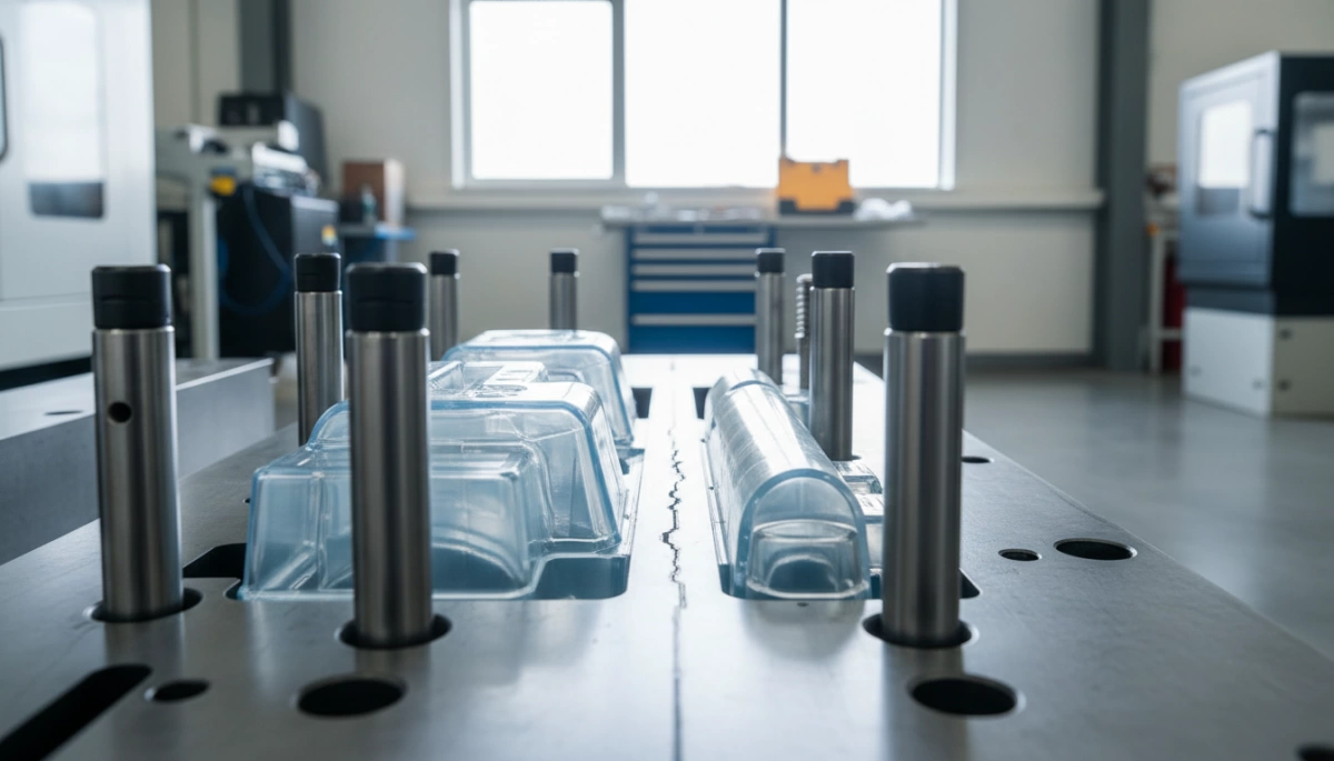
In any injection mold, guiding and alignment parts are what keep everything accurate and repeatable. If these are off, you get flash, mismatches, and rejected parts.
Guide pins, bushings, and support pillars
The main injection mold components that control alignment are:
- Guide pins (leader pins): Fixed to one mold half, they enter guide bushings on the other half to align the core and cavity every cycle.
- Guide bushings: Hardened sleeves that keep the pins running smooth and precise, even under high clamp force.
- Support pillars / support posts: Back up the plates to prevent deflection, especially on large molds or high-tonnage presses.
Well-designed guiding systems protect sensitive parts like the runner system, ejection system, and slides and lifters from side loads and wear.
Parting line and mold alignment
The parting line is where the two mold halves meet and separate. Good mold alignment keeps this line tight and clean:
- Reduces flash and mismatch on visible surfaces
- Protects gates, ejector pins, and cooling channels from damage
- Improves overall dimensional stability and part aesthetics
On tools for higher-precision work or for export production, we often tighten tolerances on guide pins and bushings and use extra support pillars to keep the parting line dead accurate over long runs. If you’re planning a new project or sourcing tooling from a plastic injection molding company in China, make sure the supplier treats alignment hardware as critical, not optional—this is where long-term mold performance is won or lost.
Venting and Auxiliary Features in an Injection Mold
Venting and auxiliary features are small details that decide whether an injection mold runs stable or gives you constant defects. I always treat vents, locating rings, and support pillars as “hidden heroes” in the mold design.
Vents: Letting Air and Gas Escape
If air and gas can’t escape, you’ll see burns, short shots, or poor surface finish. Venting is not optional.
Main venting methods:
- Parting line vents – tiny gaps along the parting line to release air.
- Pin vents – air escapes through ejector pin clearances.
- Rib/core vents – micro vents at deep ribs and pockets.
- Vacuum or assisted vents – for tight-tolerance or high-gloss parts.
Key venting rules:
- Deep ribs, long flow paths, and thin walls need aggressive venting.
- Vent land is shallow enough so plastic doesn’t flash but deep enough to release air.
- Regular cleaning is critical; vents easily clog with resin or additives.
| Venting Issue | Typical Defect | Fix |
|---|---|---|
| Poor vent layout | Burn marks, black spots | Add vents at flow ends and weld lines |
Materials Used in Injection Mold Components
When I design or source parts of an injection mold, I treat material selection as a profit lever, not just a technical detail. The steel you choose directly affects mold life, part quality, and cycle time.
Common steels for injection mold components
For most injection mold components (core, cavity, inserts, slides):
-
P20 steel
- Pre-hardened tool steel
- Good machinability, decent polishability
- Ideal for medium-volume tools and larger molds
- Common for general-purpose consumer, automotive, and appliance parts
-
H13 steel
- Hot-work tool steel with strong toughness and heat resistance
- Handles repeated thermal shock well
- Used for high-pressure, high-temperature applications and high-volume production
- Great for core and cavity inserts, especially in aggressive molding conditions
-
S136 (or equivalent stainless mold steel)
- Corrosion-resistant, high-purity stainless steel
- Excellent for high-gloss surfaces, optical parts, and medical components
- Good for molds running corrosive plastics or in humid environments
We usually combine these steels with heat treatment, nitriding, or surface coatings (like hard chrome, PVD) to boost wear resistance, corrosion resistance, and polish quality.
If you want to go deeper into steel choices and heat treatment options, I’ve broken this down in detail on our page about injection moulding mould material selection.
How we choose mold materials
When I pick materials for a specific injection mold, we weigh:
-
Production volume
- Low–medium volume: P20 or similar pre-hardened steels to save on cost and lead time
- High volume / multi-cavity: H13, S136, or other fully hardened steels for long tool life
-
Part complexity and geometry
- Thin walls, micro-features, or tight tolerances: higher-quality, stable steels with good machinability and polish (H13, S136)
- Complex slides and lifters, high wear zones, or abrasive materials: hardened inserts, surface treatments
-
Plastic material and additives
- Corrosive or filled resins (PVC, flame-retardant, glass-filled): corrosion-resistant steels like S136 and protective coatings
- High-temperature materials: hot-work steels like H13
-
Surface finish requirements
- Mirror polish for lenses or cosmetic parts: premium stainless tool steels (S136 class)
- Textured or standard finishes: P20/H13 is usually enough
The goal is always the same: select mold base plates, core and cavity steel, and inserts that meet the lifetime and quality targets without over-engineering the tool or blowing the budget.
How Mold Components Work Together in Injection Molding
In a real production run, every part of an injection mold has a job, and they all have to work in sync. Here’s how the typical step-by-step cycle runs and how mold design affects your part quality and efficiency.
Step-by-step injection molding cycle
-
Clamping
- The mold base, clamp plates, guide pins, and bushings bring the A-side (cavity) and B-side (core) together.
- Proper mold alignment at the parting line is critical here to avoid flash and uneven walls.
-
Injection
- Molten plastic flows from the machine nozzle into the sprue bushing, through the runner system, then through the gates into the core and cavity.
- The shape and size of runners and gate types (edge, pinpoint, submarine) control:
- Fill balance
- Flow marks
- Weld lines
- Cycle time and pressure
- If you want the full picture, I break this down in detail in our guide on how injection moulding works step-by-step.
-
Packing & holding
- The cavity and core are fully filled and then packed under pressure.
- Good venting and rigid support pillars prevent burn marks, sinks, and part deformation.
-
Cooling
- Cooling channels in the mold plates control how quickly and evenly the part solidifies.
- Smart cooling design cuts cycle time and reduces warpage and shrink variation.
-
Mold opening
- The clamp opens, separating cavity and core at the parting line.
- Slides and lifters retract to clear undercuts and release the part.
-
Ejection
- The ejection system (ejector pins, sleeves, blades, ejector plates) pushes the part off the core.
- Proper pin layout and pin size avoid push marks, cracks, or sticking.
How design impacts quality and efficiency
- Core and cavity design affect surface finish, dimensional accuracy, and how easily the part releases.
- Runner and gate design drive material usage, cycle time, and cosmetic quality.
- Cooling system design often decides your real capacity: a well-cooled mold can run seconds faster per shot.
- Ejector layout influences scrap rate and how stable the process is at higher speeds.
- Guiding and alignment components protect the mold from wear and keep dimensions consistent over long runs.
When I design an injection mold, I treat every component—core, cavity, runner system, cooling channels, ejector system, guide pins—as part of a single process machine. If one piece is weak, you pay for it in scrap, downtime, or higher cycle times.
Common Issues and Maintenance Tips for an Injection Mold
Even a well-designed injection mold will cause trouble if the key components aren’t aligned, cleaned, and protected properly. From my experience running jino injection molding production, most quality issues trace back to a few classic problems.
Typical Defects Linked to Mold Components
-
Flash on parting line
- Usually caused by worn guide pins, poor mold alignment, low clamp force, or damaged parting line.
- Fix: rework or polish the parting surface, replace worn alignment components, verify clamping tonnage.
-
Short shots or burn marks
- Often due to blocked vents, undersized venting, or poor runner and gate design.
- Fix: clean and deepen vents (without causing flash), adjust gate size, check air traps.
-
Warping and sinks
- Linked to unbalanced or poorly placed cooling channels, or worn core and cavity surfaces.
- Fix: optimize cooling layout, ensure equal cooling on core and cavity, polish damaged areas.
-
Ejection marks and deformation
- Caused by wrong ejector pin layout, rough pin surfaces, or late/fast ejection.
- Fix: reposition pins to thicker regions, polish ejectors, tune ejection speed and timing.
If you’re battling recurring defects, it’s worth pairing mold checks with a structured process review like in this practical guide on troubleshooting injection moulding defects.
Maintenance Tips for Mold Longevity
To keep an injection mold running stable for high volumes:
-
Clean regularly
- Remove resin residue, rust, and gas buildup from cavity, core, vents, gates, and runners.
- Use proper mold cleaners; avoid scratching critical surfaces.
-
Lubricate moving parts
- Lightly oil guide pins, slides, lifters, ejector systems with mold-safe lubricants.
- Don’t over-grease near the cavity area to avoid contamination.
-
Inspect wear points
- Check parting line, gate areas, ejector pins, and sprue bushings for wear or damage.
- Replace worn components before they start causing flash or dimensional drift.
-
Protect during storage
- Apply anti-rust spray, close molds fully, and store in a dry environment.
- Tag molds with last resin used, cycle count, and maintenance history.
-
Standardize a maintenance schedule
- For high-cavitation or high-volume tools, set preventive maintenance by cycle count, not by “when there’s a problem.”
- We typically define different levels: quick clean, full teardown, and detailed inspection.
If you’re planning long-term production and want realistic expectations on cycle times and upkeep, you can cross-check with our overview on how long injection moulding takes from cycle to cycle.
With disciplined maintenance and fast reaction to early defects, a properly built injection mold from a manufacturer like jino injection molding can run millions of cycles with stable part quality and minimal downtime.
 English
  French
  German
  Spanish
  Italian
  Polish
  Russian
  Japanese
  Korean
  Arabic
  Dutch
Dutch  Portuguese
  Swedish
  Norwegian
  Belarusian
  Armenian