
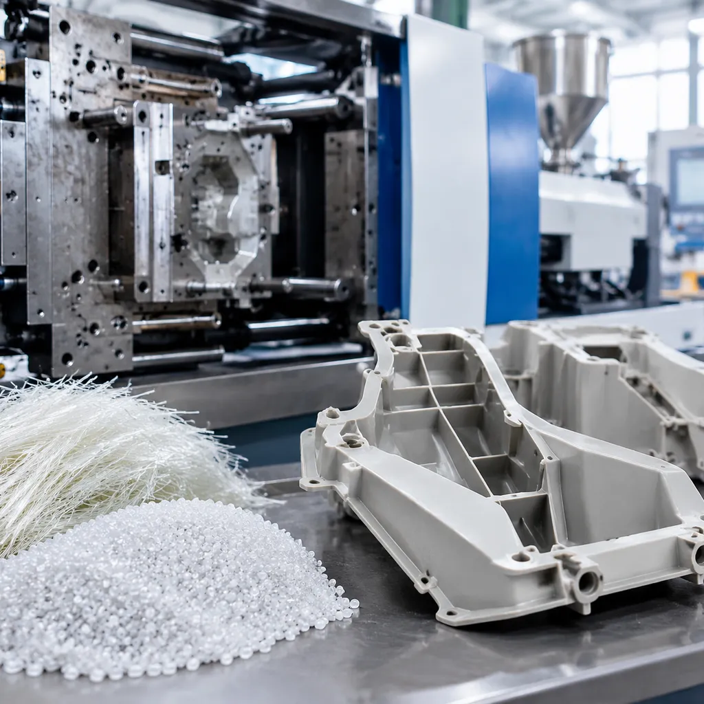
Are you struggling with fiber floating, severe tool wear, or warped parts?
You’re not alone. Mastering ABS+GF injection moulding can be a manufacturing headache if your processing parameters and mold designs are even slightly off.
The good news? It doesn't have to be guesswork.
In this guide, you’ll discover the exact temperature settings, gating strategies, and troubleshooting steps needed to produce high-strength parts with a flawless surface finish.
If you want to optimize your ABS+GF injection moulding process and cut defect rates for good, let’s dive right in.
What is ABS+GF? Material Properties and Reinforcement Mechanics
Standard ABS is a versatile, impact-resistant terpolymer, but demanding structural applications quickly push its limits. When we process ABS+GF injection moulding, we introduce short, chopped glass fibers into the amorphous ABS matrix to drastically shift its mechanical profile. The glass fibers act as a load-bearing skeleton, while the ABS resin binds the fibers and transfers mechanical stress across the component.
- Polymer Matrix: Acrylonitrile-Butadiene-Styrene (ABS) provides base toughness, chemical resistance, and processability.
- Reinforcement Phase: E-glass fibers (typically 10% to 30% loading by weight) mechanically bond to the matrix via specialized coupling agents.
- Load Distribution: Applied mechanical stresses transfer from the ductile ABS matrix to the rigid, high-modulus glass filaments.
How Glass Fiber Modifies Standard ABS (10% to 30% GF Loading)
Varying the fiber fraction tailors the polymer to specific mechanical requirements:
- ABS-GF10 (10% Glass Fiber): Delivers a moderate stiffness upgrade with minimal processing friction and manageable surface cosmetic changes.
- ABS-GF20 (20% Glass Fiber): The balanced benchmark for structural housings. It doubles rigid performance while keeping melt flow manageable.
- ABS-GF30 (30% Glass Fiber): Delivers peak tensile and flexural stiffness for heavy-duty components, though it requires strict processing controls to handle high melt viscosity and tool abrasion.
Mechanical Shifts: Modulus, Strength, and HDT
The structural changes between unfilled ABS and glass fiber reinforced ABS yield significant improvements in mechanical and thermal performance:
| Property Metric | Unfilled ABS | ABS + 20% GF | ABS + 30% GF |
|---|---|---|---|
| Tensile Modulus (MPa) | 2,100 – 2,400 | 5,500 – 6,500 | 7,500 – 9,000 |
| Flexural Strength (MPa) | 65 – 75 | 110 – 130 | 140 – 160 |
| Heat Deflection Temp (HDT @ 1.8 MPa) | ~80°C – 85°C | ~98°C – 102°C | ~103°C – 108°C |
| Linear Mold Shrinkage (%) | 0.4% – 0.7% | 0.15% – 0.3% (Flow) | 0.1% – 0.25% (Flow) |
ال heat deflection temperature ABS profile improves by nearly 20°C to 25°C at high load, allowing these parts to maintain structural rigidity in elevated thermal environments without creeping or sagging.
The Trade-offs: Impact, Cosmetics, and Shrinkage
Reinforcing ABS with glass fiber introduces specific engineering trade-offs that we account for during tooling and part design:
- Impact Resistance Reduction: Notched Izod impact values drop significantly compared to virgin resin. Fiber ends create localized stress concentration points within the polymer matrix, reducing the energy-absorbing ductility of the butadiene phase.
- Surface Gloss Loss: Fiber migration to the melt front breaks the typical resin skin layer, leading to visible surface roughness and a matte texture.
- Anisotropic Shrinkage: ال anisotropic shrinkage rate is the primary driver of part deformation. Fibers align parallel to the melt flow direction, causing shrinkage of 0.15% to 0.25% along the flow path, while cross-flow shrinkage remains higher at 0.35% to 0.55%. This differential rate requires precise gate placement to mitigate warp.
Key Processing Parameters for ABS+GF Injection Moulding
Dialing in the process window for glass fiber reinforced ABS is completely different from running neat ABS. Glass fibers increase melt viscosity, raise shear sensitivity, and drastically change how the melt cools in the cavity. We optimize every stage of the cycle to keep fiber length intact while locking in tight tolerances.
Moisture Control and Resin Drying
ABS is inherently hygroscopic, and adding glass fibers makes moisture control even more critical. Moisture on the fiber surface turns to steam inside the barrel, leading to severe splay, silver streaking, and polymer matrix degradation.
- Resin pre-drying temperature: 80°C to 90°C (176°F to 194°F)
- Drying time: 2 to 4 hours in a desiccant dryer
- Dew-point requirement: -40°C (-40°F) or lower
- Target moisture content: Below 0.02% (200 ppm)
Standard hopper dryers simply pull ambient moisture on humid days. We always run closed-loop desiccant dryers to ensure stable melt viscosity.
Barrel and Melt Temperature Profiles Across Heating Zones
Abrasive resin injection molding requires a flat to gently ascending heat profile. If the rear zones are too cold, unmelted pellets create intense mechanical shear that crushes glass fibers before they melt. If the front zones run too hot, the ABS matrix degrades and discolors.
| Machine Zone | ABS GF20 Processing Parameters | ABS GF30 Processing Parameters |
|---|---|---|
| Feed Zone (Rear) | 200°C – 220°C (392°F – 428°F) | 210°C – 230°C (410°F – 446°F) |
| Compression Zone (Middle) | 220°C – 235°C (428°F – 455°F) | 225°C – 240°C (437°F – 464°F) |
| Metering Zone (Front) | 230°C – 245°C (446°F – 473°F) | 235°C – 250°C (455°F – 482°F) |
| Nozzle | 225°C – 240°C (437°F – 464°F) | 230°C – 245°C (446°F – 473°F) |
| Actual Melt Temperature | 230°C – 250°C (446°F – 482°F) | 240°C – 255°C (464°F – 491°F) |
Mold Temperature Optimization
Mold temperature for ABS GF dictates part appearance and structural integrity. A cold tool causes the resin skin to freeze instantly, locking glass fibers against the cavity wall and leaving a visible floating fiber defect.
- Recommended tool temperature: 70°C to 95°C (158°F to 203°F).
- Surface finish benefits: Higher tool temperatures keep the outer polymer layer molten long enough to bury glass fibers beneath a resin-rich cosmetic skin.
- Cycle time trade-off: Running warmer water circuits adds cooling seconds, so we engineer conformal or high-flow water channels to balance cycle time against part quality. Evaluating these thermal cycle trade-offs is a core factor when comparing injection and non-injection competition costs on production projects.
Injection Speed and Pressure Profiles
Controlling injection speed and shear stress prevents fiber attrition. High velocity through narrow gates breaks long fibers into short dust, ruining mechanical strength.
- Multi-stage velocity profile: Start slow as the melt enters the gate to prevent gate blush and jetting. Ramp to medium speed through thick wall sections, then drop speed to 15–20% right before switchover to prevent flashing and burn marks.
- ضغط الحقن: Typically set between 70 and 120 MPa depending on wall thickness and flow length.
- Packing pressure and time: Apply 50% to 70% of peak injection pressure. We hold packing until the gate freezes to control the anisotropic shrinkage rate and stop post-mold sink without overpacking the gate area.
Back Pressure and Screw Recovery Settings
Aggressive screw rotation grinds glass fibers against the barrel wall, turning reinforced pellets into unreinforced dust. We set recovery parameters strictly to preserve fiber integrity:
- Back pressure: 0.3 to 0.8 MPa (3 to 8 bar hydraulic). Use only enough pressure to homogenize the melt and prevent air entrainment.
- Screw speed (RPM): Keep screw rotation slow, between 30 and 50 RPM.
- Suck-back (decompression): Limit to 2 to 5 mm. Excessive decompression pulls air past the nozzle tip, causing silver streaks on the next shot.
Mold Design and Tooling Strategies for Abrasive Resins
Glass fibers act like micro-abrasives under high injection pressures. When running ABS+GF injection moulding, standard mold builds wear out quickly, leading to dimensional drift, flash, and surface flaws. We are a professional injection molding manufacturer and supplier, and our approach relies on rugged tool architectures, optimized flow channels, and tailored venting to protect mold life and keep parts within tolerance.
Tool Steel Selection and Surface Treatments
Standard pre-hardened steels like P20 degrade rapidly when handling abrasive resin injection molding. For long-term production runs, we build high-wear core and cavity inserts using premium through-hardened tooling alloys.
- Hardened Mold Steel H13 (48–52 HRC): Our standard workhorse for glass-filled resins, offering exceptional toughness and resistance to thermal fatigue.
- S7 Shock-Resisting Steel (54–56 HRC): Ideal for intricate core pins, slides, and fragile shut-offs that must resist high impact and shearing forces.
- D2 Tool Steel (58–60 HRC): Best suited for high-wear gate inserts and runner blocks where friction is continuous.
- PVD and TiN Coatings: Applying a thin Physical Vapor Deposition (PVD) or Titanium Nitride (TiN) layer (3–5 microns) dramatically improves tool steel wear resistance and lowers surface friction in tight ejection areas.
Gate Location and Geometry
Glass fibers shear and break when squeezed through restrictive gate orifices, leading to compromised mechanical strength and severe gate erosion injection molding.
- نوع البوابة: Fan gates, edge gates, and heavy-duty direct sprues perform best. Pin-point and sub-gates must be enlarged by at least 20–30% compared to unfilled ABS specs.
- Location Strategy: We place gates along the thickest wall sections to fill from thick to thin. This directs flow parallel to primary stress vectors, cutting down internal stresses and fiber disorientation.
- Shear Control: Generous entry radiuses and streamlined gate transitions prevent localized resin overheating and preserve fiber aspect ratios.
| Tooling Feature | Unfilled ABS Standard | ABS+GF Optimized Standard | Engineering Purpose |
|---|---|---|---|
| Cavity / Core Steel | P20 / 718H (28–32 HRC) | Hardened H13 / S7 (48–54 HRC) | Prevents wash-out and erosion |
| Gate Land Length | 0.75 mm – 1.0 mm | 0.5 mm – 0.8 mm | Minimizes localized pressure drops |
| Runner Profile | Trapezoidal or Full-Round | Full-Round Only | Reduces shear stress and fiber fracture |
| Vent Depth | 0.04 mm – 0.05 mm | 0.025 mm – 0.035 mm | Prevents burn marks without causing flash |
Runner Systems and Cold Slug Placement
Full-round runners provide the most consistent velocity profile, minimizing boundary-layer friction that fractures glass fibers. Trapezoidal runners are acceptable on simple two-plate tools, but full-round designs maintain melt temperature and minimize pressure drops far more reliably.
- Cold Slug Wells: We position generous cold slug wells at every runner intersection and directly opposite the main sprue. These wells capture cold slugs before they reach the cavity, preventing localized clogs and surface blemishes.
- Runner Transitions: Every turn in the runner system features large radii rather than sharp 90-degree corners to keep flow laminar.
Venting Calculations to Prevent Burns and Voids
Because glass-filled ABS fills under high pressures, trapped gas quickly leads to dieseling, burning, and voids. Proper venting prevents structural degradation and surface burn marks that often require العيوب في قولبة الحقن وأسلوب حلها during production trials.
- Vent Depth: We machine vent depths to 0.025–0.035 mm. Glass-filled ABS resists flashing better than base ABS, but oversized vents will still flash over extended runs.
- Vent Land: A short land length of 1.0–1.5 mm connects the cavity to a drop-off channel vented directly to the atmosphere (0.8–1.0 mm deep).
- Blind Area Venting: We route ejector pin flats and porous steel inserts into deep ribs and the final points of fill to exhaust trapped gases cleanly.
Troubleshooting Common Defects in ABS+GF Injection Moulding

Processing glass-filled ABS presents unique challenges compared to standard unfilled resins. Adding glass fibers changes melt rheology, thermal conductivity, and volumetric shrinkage. Below is how we troubleshoot and resolve the most persistent molding defects on the shop floor.
Eliminating Floating Fibers (Silver Streaks and Rough Surface Texture)
A floating fiber defect happens when glass fibers push through to the part surface, creating silver streaks, matte patches, or an abrasive texture. This occurs during fountain flow: the resin freezes too fast against a cold cavity wall, leaving stiff fibers exposed before an unreinforced resin skin layer can form.
- Raise the mold temperature: Increasing the mold temperature for ABS GF to 80°C–90°C delays the surface freeze layer, allowing the molten ABS matrix to fully encapsulate the fibers.
- Increase injection speed: Higher shear heats the flow front and pushes the pure resin skin against the tool wall.
- Optimize melt temperature: Keep the melt fluid enough to minimize melt fracture while preventing resin degradation.
Managing Anisotropic Shrinkage and Post-Mold Warpage
Glass fibers align along the melt flow direction, producing an anisotropic shrinkage rate. Shrinkage parallel to the flow typically drops to 0.1%–0.2%, while shrinkage perpendicular (transverse) to the flow remains around 0.4%–0.6%. This directional difference drives severe fiber orientation warpage.
| عامل الانكماش | Flow Direction (Parallel) | Transverse Direction (Perpendicular) | Primary Corrective Action |
|---|---|---|---|
| معدل الانكماش | Low (constrained by fibers) | High (matrix dominated) | Rebalance gate locations |
| Cooling Behavior | Fast heat transfer via fiber | Slower localized cooling | Optimize conformal cooling |
| Defect Risk | Bowing along flow axis | Cross-axis twisting | Adjust hold pressure profiles |
To control post-mold warpage:
Re-position gates to ensure balanced flow paths and symmetric filling patterns.
Use differential mold temperatures between cavity and core halves to counteract directional bowing.
Step down packing pressure gradually to minimize built-in residual stresses.
Overcoming Weld Line Degradation Caused by Poor Fiber Entanglement
Where two flow fronts meet, the glass fibers orient parallel to the knit line rather than crossing it. This causes severe weld line strength reduction, often cutting structural load capacity at the seam by 40% to 60% compared to the rest of the part.
- Relocate gates: Move injection points so weld lines fall into low-stress, non-functional zones.
- Elevate melt front temperature: Increase injection speed right before the fronts meet to promote molecular diffusion between polymer chains.
- Add overflow tabs: Force the initial cold fronts and misaligned fibers out of the primary part cavity into external overflow tabs that are trimmed off later.
- Vent parting lines properly: Evacuate trapped gas at the merge point so the fronts knit without micro-voids or burning.
Mitigating Machine and Tool Wear (Screw Barrel Abrasion and Gate Erosion)
التعامل abrasive resin injection molding causes steady physical erosion over high production volumes. The rigid glass fibers act like micro-cutters inside the injection unit and tooling. As our facility تزيد من قدرة إنتاج القولبة for structural components, managing machine and tool wear is critical for holding dimensional tolerances over time.
- Counter gate erosion injection molding: Small pin gates wash out quickly under high-velocity fiber flow. We widen gate lands, add generous entry radii, and build interchangeable gate inserts using hardened mold steel H13 heat-treated to 50–54 HRC.
- Upgrade the injection unit: Standard nitrided barrels wear out fast. We pair bimetallic barrels featuring tungsten carbide linings with CPM tool steel screws to resist continuous abrasion.
- Apply surface coatings: Coat cavity inserts and runner turn points with Physical Vapor Deposition (PVD) treatments like Titanium Nitride (TiN) or Diamond-Like Carbon (DLC) to maximize overall tool steel wear resistance.
DFM Guidelines for ABS+GF Injection Moulding
تصميم أجزاء لـ ABS+GF injection moulding requires a strict focus on how glass fibers behave inside the cavity. Glass reinforcement cuts volumetric shrinkage, but it introduces directional stiffness and anisotropic tendencies that make standard unreinforced design rules obsolete. When we تصميم قالب لحقن البلاستيك with glass-filled ABS, we prioritize uniform flow dynamics to prevent warpage, internal stress, and premature tool damage.
Wall Thickness Uniformity and Transition Radii
Non-uniform walls lead directly to differential cooling and severe part warpage due to fiber alignment differences.
- Target Wall Thickness: Maintain a nominal wall between 2.0 mm and 3.5 mm. Going below 1.5 mm spikes injection pressure and shears fibers, while sections exceeding 4.0 mm trap internal heat and induce structural voids.
- Thickness Transitions: When steps in wall thickness are unavoidable, apply gradual chamfers or tapers with a maximum slope of 3:1 to keep melt velocity uniform.
- Transition Radii: Avoid sharp internal corners. Maintain an inside radius of at least 0.5 to 0.6 times the nominal wall thickness (minimum 0.8 mm to 1.2 mm). Generous radii drop notch sensitivity, relieve mold stress concentrations, and minimize fiber fracture during high-velocity filling.
Draft Angles Required for Stiffer, Fiber-Filled Walls
Glass fibers make ABS rigid and reduce standard thermal shrinkage around mold cores. The resin will not shrink away from cavity walls as freely as unfilled ABS, resulting in heavy drag, surface scratching, and high ejection loads.
| Feature Type | Unfilled ABS Draft | ABS+GF Draft Requirement | Key Reason |
|---|---|---|---|
| Standard Core & Cavity Walls | 1.0° – 1.5° | 2.0° – 3.0° | Overcomes abrasive drag and prevents part hang-up |
| Deep Pockets (> 50 mm) | 1.5° – 2.0° | 3.0° – 5.0° | Mitigates severe pin push-through and core binding |
| Textured / Matte Surfaces | 1.0° per 0.02 mm depth | Add 1.5° to 2.0° base draft | Stops floating fibers from tearing out tool grain |
- Always polish draw surfaces along the line of draw to an SPI-B1 finish or better to ensure clean ejection.
Rib-to-Wall Ratios to Prevent Read-Through and Sink Marks
Because glass-filled resins exhibit lower overall shrinkage, sink marks over ribs look different than in standard ABS. Instead of deep depressions, fiber orientation over rib intersections causes surface read-through, visible shadows, and localized stress risers.
- Rib Base Thickness: Keep the rib base thickness between 40% and 50% of the adjoining nominal wall thickness. Exceeding 50% creates heavy mass concentrations that disrupt fiber flow and cause cosmetic read-through on exterior cosmetic faces.
- Rib Height Limits: Restrict maximum rib height to 2.5 to 3.0 times the nominal wall thickness. Overly tall ribs freeze prematurely at the tips, trapping air and leading to short shots.
- Rib Draft and Spacing: Apply at least 1.5° of draft per side on all structural ribs. Space parallel ribs at a distance of at least 2.0 times the nominal wall thickness to ensure adequate cooling steel and prevent thermal hot spots inside the tool.
Industrial Applications: Where ABS+GF Outperforms Standard Resins
Unfilled ABS provides toughness and reasonable impact resistance, but it softens and deflects under sustained mechanical loads or elevated temperatures. When an application demands structural rigidity, tight dimensional retention, and dimensional stability, we rely on ABS+GF injection moulding. Adding glass fibers turns standard ABS into an engineering-grade choice for tough working conditions across multiple industries.
Automotive Structural Trim and Under-the-Hood Housings
Vehicle components near the engine bay or exposed to direct sun face thermal cycling and continuous road vibration. Standard grades warp or develop rattles over time. Reinforced ABS handles these environments by raising the thermal deflection ceiling and preventing mechanical creep:
- HVAC duct mountings and vent louvers: Retain their alignment without sticking during high-heat operation.
- Sensor brackets and wire harness tracks: Maintain firm clamping force under constant engine vibration.
- Structural substrates for interior assemblies: Prevent squeaks and rattles by eliminating flex in multi-piece assemblies.
Industrial Power Tool Casings and High-Stiffness Structural Brackets
Power tools must endure drop impacts while keeping high-RPM motors and internal gears in precise alignment. A flexible casing lets internal gears skip teeth, causing early motor failure. Glass fiber reinforced ABS provides the high flexural modulus needed to hold internal drive trains secure:
- Impact driver and drill clamshell housings: Resist torsional twist when the motor hits peak torque.
- Structural mounting plates: Support batteries and motor armatures without bending.
- Equipment chassis: For larger industrial shells where part weight and section thickness must be optimized alongside solid ABS+GF components, we also evaluate قولبة الحقن بالرغوة البنائية to hit specific structural targets.
Precision Electronic and Meter Frames
Internal chassis for sensitive electronics require close tolerances that remain stable over years of field use. Unreinforced polymers creep and shift, risking PCB strain or lens misalignment. ABS+GF provides an uncompromising foundation:
- Utility meter bezels and housings: Prevent outdoor thermal distortion and secure internal sealing gaskets.
- Internal optoelectronic chassis: Lock laser diodes, sensors, and optical lenses into fixed alignment.
- Handheld testing device bodies: Provide a rigid, drop-resistant skeleton that protects delicate internal solder joints from shock.
Engineering High-Precision ABS+GF Components with Jino Injection Molding
Scaling production with glass-filled resins requires experienced tooling and tight machine control. We are a professional injection molding manufacturer and supplier equipped to handle the unique challenges of fiber-reinforced polymers from concept to full production runs. By combining robust mold designs with modern press technology, we eliminate typical processing defects like gate erosion, floating fibers, and unpredicted warpage.
In-House DFM and Mold Flow Simulation for Fiber Orientation
Predicting how fibers behave inside the cavity is critical before cutting steel. Our engineering team runs comprehensive Moldflow simulations to map fiber orientation, identify weld lines, and prevent anisotropic shrinkage.
- Gate Location Mapping: Pinpointing gate positions to align fibers along primary load-bearing axes.
- Weld Line Management: Relocating knit lines away from structural stress zones to preserve mechanical integrity.
- Warpage Prediction: Evaluating differential shrinkage between flow and cross-flow directions to refine wall thickness.
Hardened Tooling Manufacturing and Precision Press Capabilities
Processing abrasive resins calls for durable tooling and repeatable injection units. Our Jino precision tooling solutions utilize hardened tool steel such as H13 and S7, often paired with PVD and TiN surface coatings to withstand continuous fiber friction.
| Tooling & Machine Parameter | Standard Specification | Operational Benefit |
|---|---|---|
| Mold Steel Core/Cavity | Hardened H13 (48–52 HRC) | Resists abrasive wear and gate erosion |
| Gate Inserts | Replaceable sub-inserts | Allows quick maintenance without retooling |
| Clamping Equipment | High-rigidity toggle systems | Maintains uniform parting line pressure |
| Bimetallic Barrels | Carbide-lined screws | Prevents barrel wash-out from glass fillers |
Our production floor pairs this tooling expertise with stable machinery. For manufacturers seeking robust processing equipment, choosing an optimized آلة حقن صب塑形 للبيع ensures precise back pressure control, low-shear plasticizing, and minimal fiber breakage during recovery.
Production Scalability and Strict Quality Inspection Standards
We transition programs seamlessly from pilot sampling to mass production without compromising tolerances. Every batch of ABS+GF injection moulding parts undergoes systematic quality screening to verify dimensional stability and mechanical performance.
- CMM Coordinate Verification: Routine checks on critical dimensions to catch warpage trends early.
- Tensile and Impact Validation: Ensuring fiber length preservation translates to full structural strength.
- Surface Defect Audits: Inspecting for fiber exposure, flash, or sink marks under standard inspection lighting.
Frequently Asked Questions About ABS+GF Injection Moulding
How does glass fiber loading affect mold steel wear over time?
Glass fibers turn the melt into an abrasive slurry. As glass fiber reinforced ABS moves through tight gates and high-shear runner turns, it causes gate erosion and washes out parting lines.
- Standard tool steels (like P20): Wear down rapidly, leading to dimensional drift and flash within low shot counts.
- Hardened mold steel H13 (50–54 HRC): Our standard recommendation for core and cavity inserts running 10% to 30% fiber loadings.
- Surface treatments: Applying PVD or TiN coatings gives high-wear areas the tool steel wear resistance required for long production runs.
Unlike conventional processing covered in our guide on مواد خام ABS لصب الحقن, abrasive resin injection molding demands hardened tooling from day one.
What is the fastest way to resolve floating fiber marks on cosmetic surfaces?
A floating fiber defect occurs when the glass fibers fail to freeze beneath a smooth polymer skin layer, showing up as silver streaks on the part surface.
- Raise mold temperature: Boosting the mold temperature for ABS GF to 80°C–100°C delays surface skin solidification, letting the resin matrix encapsulate the fibers.
- Increase injection speed: Faster fill rates create higher shear heat near the cavity wall, forcing resin to cover the exposed fibers.
- Check drying parameters: Moisture pushes fibers to the surface. Maintain a resin pre-drying temperature of 80°C–85°C for 2 to 4 hours with a desiccant dryer.
Why does ABS+GF warp more along the flow direction than transverse to it?
The primary driver is the anisotropic shrinkage rate caused by fiber alignment during fill.
| Direction | Fiber Behavior | Shrinkage Behavior |
|---|---|---|
| اتجاه التدفق | Fibers orient parallel to the melt stream, physically restricting thermal contraction. | Low shrinkage (often 0.1%–0.3%) |
| الاتجاه العرضي | Few fibers bridge the gap, leaving the ABS matrix to shrink normally. | High shrinkage (often 0.4%–0.7%) |
This differential contraction creates internal stress, resulting in severe fiber orientation warpage in flat or thin-walled geometries.
Can regrind ABS+GF be mixed with virgin resin without sacrificing structural strength?
Yes, but we keep regrind ratios strictly between 10% and 15%.
Every granulating and remelting pass snaps the brittle fibers, reducing their aspect ratio. Shorter fibers cannot transfer mechanical loads effectively, which degrades tensile modulus, lowers the heat deflection temperature ABS parts require, and causes severe weld line strength reduction. For critical load-bearing parts, we advise using 100% virgin resin. As a professional injection molding manufacturer and supplier, we qualify any regrind blend through melt flow and mechanical testing prior to full production runs.
 Arabic
  English
  French
  German
  Spanish
  Italian
  Polish
  Russian
  Japanese
  Korean
  Dutch
Dutch  Portuguese
  Swedish
  Norwegian
  Belarusian
  Armenian